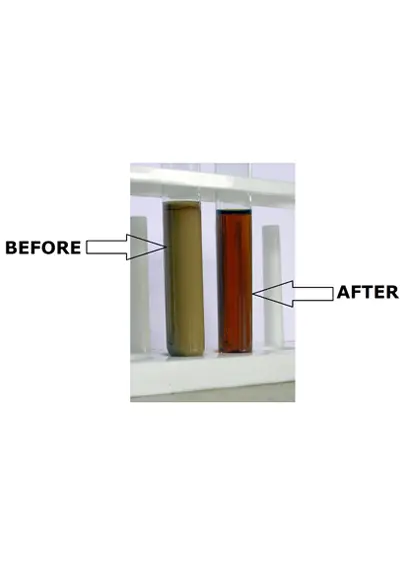
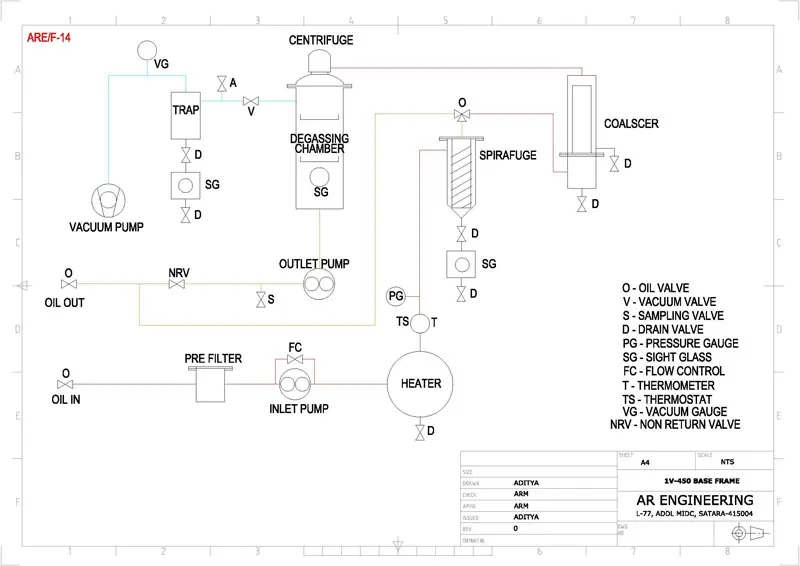
Oil Purification Systems are designed & manufactured to suit the specific requirement of the customer. Normally the oil is deteriorated by contamination of foreign particles, moisture (free & dissolved), oxidation sludge etc.
The deteriorated oil affects the performance of the equipment in which it is used because of change in properties. Different modules are designed to remove particular types of contaminations. The purification system normally consists of filtration / purification stages for economical operation. In pre filtration stage coarse particles are removed using cleanable / washable elements. In intermediate stage the major portion of the contaminants removed by using the properly selected filter elements suitable for oil to be purified. In final stage the fine contaminants are removed by special elements to suit the final application and purification level.
The free moisture removal is carried out either by gravity separation methods such as spirafuge, centrifuge or by using coalescer elements. Dissolved moisture is removed partially by coalescer elements and finally by vacuum treatment.
INDUSTRIAL OIL PURIFICATION UNITS FAQ'S QUESTIONNAIREFollowing Modules Are Used Frequently In Oil Purification Systems :
PRE FILTERS :
With suitable size perforated or wire mesh element are used to remove major portion of suspended particles.
These are used to remove magnetic impurities. These are used especially to filter the cutting oil / coolant where the magnetic dirt contaminate oil during processes such as grinding, honing, reaming etc.
These are used to remove free moisture and coarse suspended particles from oils. In these the oil is given the spiral path around the filter strainer so that vortex is formed at the bottom so that heavier particles and water are collected at the bottom and can be removed periodically by opening drain valve. The dirt is collected on the surface of the central filter element which is carried by the oil to bottom when drain valve is opened so the filter is cleaned without opening the filter chamber.
FINE FILTERS :
These filters remove free as well as emulsified water from the oil. Depending on the type of oil water can be removed to < 50 – 100 ppm. The dictionary definition of coalescence is "To grow together; to unite into one body or mass." As applied to the technology of oil water separation, coalescence is usually accomplished by a first stage of fibrous media that allows oil to pass through but attracts and "stores" the emulsified water until these tiny particles unite, or coalesce, to become large droplets of water. This free water is then released to a second stage utilizing a water repellant media. It will be provided with water drain tank, for removal of separated water periodically. Pressure gauge will be provided to indicate the clogging of filter.
These remove the particles down to desired level as per the application. Depending on the filtration level, viscosity, working temperature & pressure and oil compatibility the type of filter media can be selected. Some of the types of filter media are pleated paper, molded cellulose, stainless steel etc. Besides selecting proper filter media the fitment of the elements is very important to ensure the proper filtration. Differential pressure gauge or pressure gauge before filter is required to indicate the clogging of filters so that filter element can be used to appropriate capacity.
In centrifugal Filter oil passes through a rotor spinning at high speed so that particles in the oil are deposited on the inner wall of rotor to form a dense cake. It is particularly more suitable for permanent fitting on the oil tank. It has more dirt holding capacity as compared to normal depth filter of fine micron rating. Centrifugal separation is most suitable way to remove small hard metallic particles.
OIL CIRCULATION SYSTEM :
It is required to circulate the oil during filtration process. Normally it is with oil circulation pump or pumps with necessary valves and piping for easy operation and maintenance.


TECHNICAL DATA. SHEET FOR INDUSTRIAL OIL PURIFICATION SYSTEMS |
|||||||
| FLOW RATE | LPH |
240 |
500 |
750 |
1500 | ||
| MODEL | SFCV-024 |
SFCV-050 |
SFCV-075 |
SFCV-150 |
|||
| MOTOR POWER | INLET |
HP |
0.5 |
1 |
1 |
1.5 |
|
OUTLET |
HP |
0.5 |
0.5 |
0.5 |
1 |
||
VACUUM -1 |
HP |
1 |
1 |
2 |
3 |
||
| HEATER POWER | HEATER-1 |
TOTAL kW |
6 |
12 |
18 |
18 |
|
NOS x kW |
3 x 2 |
6 x 2 |
6 x 3 |
6 x 3 |
|||
HEATER-2 |
TOTAL kW |
- |
- |
- |
9 |
||
NOS x kW |
- |
- |
- |
3 x 3 |
|||
TOTAL (kW) |
6 |
12 |
18 |
27 |
|||
| FILTRATION SYSTEM | SPIRAFUGE |
FOR COARSE DIRT REMOVAL |
|||||
COALESCER |
FOR FREE WATER REMOVAL |
||||||
CENTRIFUGE |
FOR FINE PARTICLE SEPARATION |
||||||
| VACUUM PUMP DISPLACEMENT | VACUUM-1 |
m3/HR |
20 |
25 - 30 |
45 |
65 |
|
| WORKING VACUUM | mbar |
LESS THAN 10 mbar.* |
|||||
| WATER HANDLING CAPACITY | kg/hr |
0.25 |
0.3 - 0.5 |
0.9 |
1.6 |
||
Notes